Other Explicit Representation for the Orientation in Robotics: Euler Angles
In the lesson about the degrees of freedom of a robot, we learned that there are at least three independent parameters needed to express the orientation of a rigid body. In the previous lesson, we learned about the exponential coordinate representation for the orientation that is a three-parameter representation for a rotation matrix R, and parameterizes the rotation matrix using a unit axis of rotation and the angle of rotation about this axis.
There are also other explicit representations that are useful in different applications when dealing with orientations. In this lesson, we will talk about Euler Angles and will see how we can use this representation to parameterize an orientation.
This lesson is part of the series of lessons on foundations necessary to express robot motions. For the full comprehension of the Fundamentals of Robot Motions and the necessary tools to represent the configurations, velocities, and forces causing the motion, please read the following lessons (note that more lessons will be added in the future):
https://www.mecharithm.com/category/fundamentals-of-robotics/fundamentals-of-robot-motions/
Also, reading some lessons from the base lessons of the Fundamentals of Robotics course is beneficial.
ZYX Euler Angles
Consider the body frame {b} is instantaneously attached to a rigid body and was initially aligned with the space frame {s}:
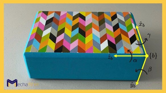
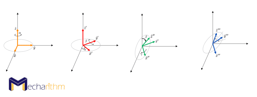
The ZYX Euler angles (α,β,γ) are specified by a rotation of the body by α about the body z-axis, then by β about the body y-axis, and finally by γ about the body x-axis. Then the final orientation of the body can be found by the multiplication of the rotation operators about the z, y, and x-axes:
The rotation operators are found in the Rotation Matrices lesson, and the above equation for the final orientation of the body can be interpreted as starting from the initial orientation when the body frame is coincident with the space frame and thus R = I, then rotate it by α about the body frame z-axis, then by β about the body frame y-axis and finally by γ about the body frame x-axis to reach the final orientation (note the order in which the rotation operators are written). Visualize this as the following consecutive rotations:
Video below shows a demonstration of the ZYX Euler angles to represent the orientation:
Now let’s solve the opposite, meaning that if we are given an arbitrary rotation matrix R ∈ SO(3) as
does there exist (α,β,γ) that satisfies R(α,β,γ) found by rotation operators above? In other words, can Euler angles represent all orientations?
To solve this, we should equate the expression for R(α,β,γ) to the given rotation matrix
From the first two elements of the first column, we can write:
and from the third element of the first row, we can write
If cos β ≠ 0 and thus β ≠ ±90o, then the expressions for β can be written as
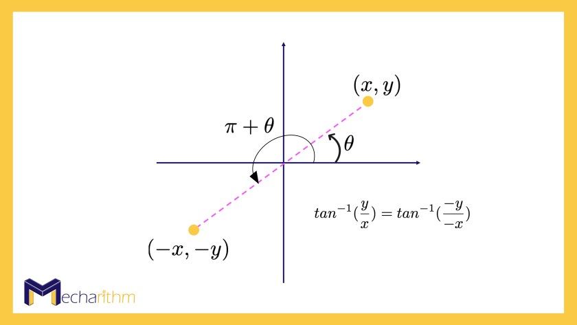
atan2(y,x) is a two-argument function that is similar to arctangent, but the difference is that since tan-1(y/x) = tan-1(-y/-x) then tan-1 only returns angles in the range (-π/2,π/2) but atan2(y,x) returns angles in the range (-π,π) and thus it is called a four-quadrant arctangent. In other words, arctangent does not differentiate between angles in the first and third quadrant as well as angles in the second and fourth quadrant (the first and the third quadrant are shown as an example), and in robotics, we prefer the four-quadrant arctangent to make the quadrant in which the angle lies clear.
Then α and γ can be found using the following equations
These equations are obtained considering that cos β ≠ 0 and thus β ≠ ±90o.
The ZYX Euler angles can be shown in the three degrees of freedom (DOFs) robotic wrist mechanism (the 3-DOF orienting mechanism) as follows:
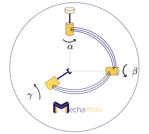
The wrist mechanism is in its zero position, meaning that all three joint angles are set to zero. The ZYX Euler angles (α,β,γ) refer to the angles of rotation about the three joint axes of the wrist mechanism, and the orientation of the end-effector can be expressed by the matrix R(α,β,γ) found above.
When β = 90o, then the wrist mechanism will be in the position where α and γ represent rotations in the opposite direction about the same vertical axis:
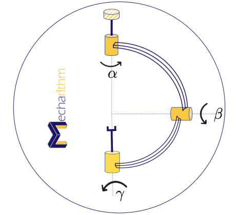
This configuration is the singularity of the ZYX Euler Angles representation for SO(3) because γ is no longer about the x-axis, and it is about the z-axis.
Now let’s find the expressions for Euler angles for a given rotation matrix R when cosβ = 0 and thus β = ±90o.
- Case 1: β = π/2 then inserting the value for β in the expression for R(α,β,γ) and then equating it to the given rotation matrix, we get
From this equation, we can see that r31 = -1 and
One possible solution is when α = 0, and gamma can be calculated using one of the equations.
- Case 2: β = – π/2 then inserting the value for β in the expression for R(α,β,γ) and then equating it to the given rotation matrix, we get
From this equation, we can see that r31 = 1 and
Then one possible solution is α = 0 and γ = atan2(-r12,r22).
β = ±90o is the singularity of the ZYX Euler Angle representation for SO(3), meaning that at those angles, there are infinitely many Euler angle representations for a given rotation matrix. This is problematic in practical applications where the robot’s controller will be confused at those configurations and can generate solutions that can cause problems.
The case where β = ±90o brings up a new discussion on other possible Euler angle representations that we call ZYZ Euler angles.
ZYZ Euler Angles Representation
If we define the home position of the wrist mechanism as the position when β = 90o (because choosing the zero position for β is arbitrary), then another three-parameter representation (α,β,γ) for SO(3) that we call ZYZ Euler angles defines the resulting orientation of the end-effector.
The ZYZ Euler angles can be defined as a sequence of rotations, first about the body’s z-axis, then about the body’s y-axis, and finally about the body’s z-axis:
You can visualize these rotations as the simulation below:
ZYZ Euler Angles Representation for the orientation is popular in robotics since most six-degree-of-freedom industrial robots have their fourth axis as a rotation about the z-axis of the fourth joint, then the fifth is a rotation about the y-axis of the fifth joint, and the final one is a rotation along the z-axis of the end-effector as depicted in the figure below:
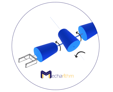
See these rotations in the simulation video below (the rotation starts from the zero position where all joint angles are zero):
Please note that these are two of the most common Euler angle representations, and different robotics companies can use different conventions for Euler Angles.
Conversely, we can say that for every rotation R ∈ SO(3), there exists a triple (α,β,γ) that satisfies R = R(α,β,γ) (given above). To solve this, we equate the expression for R(α,β,γ) to the given rotation matrix:
From the above equation, we can see that cβ = r33, and if sβ ≠ 0 and thus β ≠ ±kπ (k=0,1,2,…) then similar to before, the following solutions can be found for β, α, and γ
and
If sβ = 0 then β ± kπ (k = 0,1,2,…) then there will be two cases:
- Case 1: k is an odd integer then cβ = -1 and we have
We can say that r33 = -1 and
One possible solution is when α = 0 and γ can be found using one of the equations above.
- Case 2: k is an even integer then cβ = 1 and we have
Then r33 = 1 and
One possible solution is when α = 0 and γ can be found using one of the equations above.
If R = I (identity rotation), then using the equations above we can say that the ZYZ Euler angles (α,0,-α) can represent the identity rotation. Therefore, there are infinitely many ZYZ Euler angles that can represent this orientation, and this is considered the singularity (lack of existence of a global and smooth solution to the inverse problem) of this representation, and we know that singularities can never be eliminated in any 3-parameter representation of SO(3) (Refer to the lesson on Configuration and Configuration Space for more information).
General form of Euler Angles
In general, we can say that if rotation axis 1 is orthogonal to rotation axis 2 and rotation axis 2 is orthogonal to rotation axis 3, and axes 1 and 3 are not necessarily orthogonal to each other, then the three-parameter explicit representation for SO(3) can be expressed by Euler angles as successive rotation operators about these axes.
Example: ZXZ Euler Angle Representation for a Given Orientation
Find ZXZ Euler angles for the following orientation:
Solution: Similar to the approach for ZYX and ZYZ Euler angles, we can find the rotation matrix corresponding to the ZXZ Euler angles as
If we equate the given R to the rotation matrix from the Euler angles, then we can say that
If sβ = 1/√2 then
If sβ = -1/√2 then
So, both sets of ZXZ Euler angles of (π,π/4,π/4), and (0,-π/4,5π/4) can represent the rotation matrix for the given orientation.
Let’s watch the simulation below to actually see that these two sets of rotations actually give the same orientation:
That’s going to wrap up today’s lesson. In the next lesson, we will continue with orientation and see another explicit representation to express the orientation.
The video version of the current lesson can be watched at the link below:
References:
📘 Textbooks:
Modern Robotics: Mechanics, Planning, and Control by Frank Park and Kevin Lynch
A Mathematical Introduction to Robotic Manipulation by Murray, Lee, and Sastry
🔧 Other:
- Husam Aldahiyat (2021). Euler/Fixed Angles Properties (https://www.mathworks.com/matlabcentral/fileexchange/24247-euler-fixed-angles-properties), MATLAB Central File Exchange. Retrieved July 21, 2021.
✍️ Logo design by Minro Art Group
